<?xml version="1.0" encoding="utf-8"?><feed xmlns="http://www.w3.org/2005/Atom" ><generator uri="https://jekyllrb.com/" version="4.4.1">Jekyll</generator><link href="https://jasiek.me/feed.xml" rel="self" type="application/atom+xml" /><link href="https://jasiek.me/" rel="alternate" type="text/html" /><updated>2026-11-18T12:56:27+01:00</updated><id>https://jasiek.me/feed.xml</id><title type="html">journal of recreational computer science</title><subtitle></subtitle><author><name>Jan Szumiec</name></author><entry><title type="html">Orange FTTH, Funbox 6 and RouterOS (MikroTik)</title><link href="https://jasiek.me/2024/04/20/orange-funbox-6-routeros" rel="alternate" type="text/html" title="Orange FTTH, Funbox 6 and RouterOS (MikroTik)" /><published>2024-04-20T00:00:00+02:00</published><updated>2024-04-20T00:00:00+02:00</updated><id>https://jasiek.me/2024/04/20/orange-funbox-6-routeros</id><content type="html" xml:base="https://jasiek.me/2024/04/20/orange-funbox-6-routeros"><![CDATA[<p>Orange now offers FTTH via their whitelabelled Sagemcom router + ONT combo called <a href="https://www.softathome.com/2021/02/11/orange-poland-launches-wi-fi-6-in-new-ftth-offer-providing-the-fastest-connectivity-in-poland-with-softathome/">Funbox 6</a>.
While this works amazingly great out of the box, if you’re like me, you’d like some more control over the experience - particularly if you already own a home networking setup you are happy with.
This writeup describes how to get that done using MikroTik hardware. I’ve found MikroTik to be an excellent budget-oriented alternative to Ubiquiti’s Unifi (which has bricked some of the older
APs I owned).</p>

<h1 id="getting-the-necessary-hardware">Getting the necessary hardware</h1>

<p>Since the ONT (piece of hardware which acts as an interface converter between GPON and ethernet) is welded into the router, we want to get one which has an ethernet interface.
If you ask the operator, they will supply one. Ensure that this ends up in the notes on the order and it will be delivered by the technician during installation. It is important
that this must be supplied by the operator as it is provisioned over the network by them. If you buy a random ONT and hook it up, it will simply not work at all.</p>

<h1 id="cabling-it-up">Cabling it up</h1>

<p>The ONT has two sockets - one for the fiber and one for gigabit ethernet. The latter is connected to the WAN port (usually ether1, or port 1) of your router.</p>

<h1 id="configuration">Configuration</h1>

<p>The ethernet medium is used for multiplexing multiple services - internet access, TV and VoIP. This is accomplished by tagging each service with a different VLAN. Since we’re
interested in internet access, the VLAN tag is 35. Go to <code class="language-plaintext highlighter-rouge">Interfaces | VLAN</code> and create a new virtual interface with the following settings:</p>

<div class="language-plaintext highlighter-rouge"><div class="highlight"><pre class="highlight"><code>Name: orange-vlan35
MTU: 1500
VLAN ID: 35
Interface: ether1 (or your WAN interface)
</code></pre></div></div>

<p>Orange uses <a href="https://en.wikipedia.org/wiki/Point-to-Point_Protocol_over_Ethernet">PPPoE</a> as a transport mechanism for internet access. Once you connect an ONT, you can check if
the ONT works correctly by listening to PPPoE advertisements by going to <code class="language-plaintext highlighter-rouge">PPP | PPPoE Scan</code> and waiting a minute or so.</p>

<p>Configure your PPPoE connection by creating a new PPPoE client:</p>

<div class="language-plaintext highlighter-rouge"><div class="highlight"><pre class="highlight"><code>Name: pppoe-orange-v4
Max MRU: 1540
Interfaces: orange-vlan35
User: (username)@neostrada.pl
Password: (your password)
Profile: default
Use Peer DNS: Yes
Add Default Route: Yes
</code></pre></div></div>

<p>After creating the interface you should see the local and remote address fields being populated.</p>

<p>The last remaining step is to ensure there’s a NAT rule to translate outgoing traffic from your network onto their supplied external IP address. Go to <code class="language-plaintext highlighter-rouge">IP | Firewall | NAT</code> and
make sure there’s a rule in place:</p>

<div class="language-plaintext highlighter-rouge"><div class="highlight"><pre class="highlight"><code>Chain: srcnat
Src. Address: (your internal network subnet)
Out. Interface: pppoe-orange-v4
Action: masquerade
</code></pre></div></div>

<p>That’s it. If you’ve set up everything properly you should be able to access the internet from your internal network.</p>

<h1 id="extra-credit---ipv6">Extra credit - IPv6</h1>

<p>To set up IPv6, you need to ensure that the <code class="language-plaintext highlighter-rouge">ipv6</code> package is installed - see if that’s the case and install it by going to <code class="language-plaintext highlighter-rouge">System | Packages</code>. Once you’ve installed
it and rebooted the router, you’ll need to set up another PPPoE connection:</p>

<div class="language-plaintext highlighter-rouge"><div class="highlight"><pre class="highlight"><code>Name: pppoe-orange-v6
Max MRU: 1540
Interfaces: orange-vlan35
User: (username)@neostrada.pl/ipv6
Password: (your password, same as above)
Profile: default
Use Peer DNS: Yes
</code></pre></div></div>

<p>Create a new pool via <code class="language-plaintext highlighter-rouge">IPv6 | Pool</code>:</p>

<div class="language-plaintext highlighter-rouge"><div class="highlight"><pre class="highlight"><code>Name: orange
Prefix: ::/0
Prefix Length: 56
</code></pre></div></div>

<p>The mechanism for getting an IP address here is slightly different - you need to set up a DHCP client, by going to <code class="language-plaintext highlighter-rouge">IPv6 | DHCP Client</code>. Create a new client with the
following configuration:</p>

<div class="language-plaintext highlighter-rouge"><div class="highlight"><pre class="highlight"><code>Interface: pppoe-orange-v6
Request: prefix
Pool Name: orange
Pool Prefix Length: 64
Prefix Hint: ::/0
Use Peer DNS: Yes
Rapid Commit: Yes
</code></pre></div></div>

<p>If this is successful, you will see that a prefix has been acquired in the DHCP Client view.</p>

<p>After you apply these settings you should see that the interface is bound and that you’ve received a prefix. Go to <code class="language-plaintext highlighter-rouge">IPv6 | ND</code> and enable neighbor discovery:</p>

<div class="language-plaintext highlighter-rouge"><div class="highlight"><pre class="highlight"><code>Interface: bridge
RA Interval 200-600
Advertise MAC Address: Yes
Advertise DNS: Yes
</code></pre></div></div>

<p>Ensure that your IPv6 stack is configured for IP forwarding - go to <code class="language-plaintext highlighter-rouge">IPv6 | Settings</code>:</p>

<div class="language-plaintext highlighter-rouge"><div class="highlight"><pre class="highlight"><code>IPv6 Forward: Yes
</code></pre></div></div>

<p><code class="language-plaintext highlighter-rouge">Accept Redirects</code> should not be enabled for routers, so we want to unmark it.</p>]]></content><author><name>Jan Szumiec</name></author><summary type="html"><![CDATA[Orange now offers FTTH via their whitelabelled Sagemcom router + ONT combo called Funbox 6. While this works amazingly great out of the box, if you’re like me, you’d like some more control over the experience - particularly if you already own a home networking setup you are happy with. This writeup describes how to get that done using MikroTik hardware. I’ve found MikroTik to be an excellent budget-oriented alternative to Ubiquiti’s Unifi (which has bricked some of the older APs I owned).]]></summary></entry><entry><title type="html">Getting gitlab runner docker credentials helper working with AWS ECR</title><link href="https://jasiek.me/2020/09/16/getting-gitlab-runner-docker-credentials-helper-working-with-aws-ecr" rel="alternate" type="text/html" title="Getting gitlab runner docker credentials helper working with AWS ECR" /><published>2020-09-16T00:00:00+02:00</published><updated>2020-09-16T00:00:00+02:00</updated><id>https://jasiek.me/2020/09/16/getting-gitlab-runner-docker-credentials-helper-working-with-aws-ecr</id><content type="html" xml:base="https://jasiek.me/2020/09/16/getting-gitlab-runner-docker-credentials-helper-working-with-aws-ecr"><![CDATA[<p>Ever since I started working with Gitlab, I immediately took a liking to their build system. The CI process is defined programmatically via YAML files (ok, apart from that bit), and it runs on their build farm which is pay per use. I’m not sure if this is their original idea, or whether it was first conceived by someone else (CircleCI comes to mind), but having a build process and maintaining that being someone else’s problem sounds appealing to me.</p>

<p>Our build process builds an artefact in the form of a docker image - that image is then used to execute tests, and, if those pass - gets published to an AWS ECR repository. Getting this to work nicely and seamlessly has proven a bit challenging. </p>

<p><img src="/uploads/aws-ecs-cred-helper.svg" alt="" title="Circus on wheels" width="641" height="531" /></p>

<h2 id="step-1---build-a-custom-ci-image">Step 1 - build a custom CI image</h2>

<p>I’ve started by building a custom image, which in addition to having docker installed, also has <code class="language-plaintext highlighter-rouge">awscli</code> installed, and a bunch of other common dependencies. What to include is largely up to you, but you’ll need to install the <code class="language-plaintext highlighter-rouge">amazon-ecr-credential-helper</code> binary. This component will talk to the AWS API and generate credentials which other containers can use to talk to ECR.</p>

<div class="language-plaintext highlighter-rouge"><div class="highlight"><pre class="highlight"><code>FROM docker:19
RUN curl -o /usr/bin/docker-credential-ecr-login https://amazon-ecr-credential-helper-releases.s3.us-east-2.amazonaws.com/0.4.0/linux-amd64/docker-credential-ecr-login
RUN chmod a+x /usr/bin/docker-credential-ecr-login
RUN mkdir /root/.docker
RUN echo '{"credsStore":"ecr-login"}' &gt; /root/.docker/config.json
ENV AWS_DEFAULT_REGION eu-west-2
</code></pre></div></div>

<p>Additionally, you need to tell docker that there is a credential helper to use - this is accomplished by modifying <code class="language-plaintext highlighter-rouge">~/.docker/config.json</code>. You may need to set the default AWS region, unless you intend to set it dynamically through the <code class="language-plaintext highlighter-rouge">variables</code> section of the gitlab CI config file. The region setting is used by the credential helper to generate credentials - and has nothing to do with anything else.</p>

<p>The image you build and push to a repository will be used by other build processes, so it’s best if you note down its reference.</p>

<h2 id="step-2---use-your-custom-build-image">Step 2 - use your custom build image</h2>

<p>Simply replace any <code class="language-plaintext highlighter-rouge">image</code> declaration you might have, or add one to your <code class="language-plaintext highlighter-rouge">.gitlab-ci.yml</code> file, like this:</p>

<div class="language-plaintext highlighter-rouge"><div class="highlight"><pre class="highlight"><code>image: 340000007665.dkr.ecr.eu-west-2.amazonaws.com/ci:latest
</code></pre></div></div>

<p>This will tell <code class="language-plaintext highlighter-rouge">gitlab-runner</code> to use that image instead of the stock GitLab CI image.</p>

<h2 id="step-3---provision-some-boxes-and-set-up-iam-roles">Step 3 - provision some boxes and set up IAM roles</h2>

<p>Use your preferred method to bring up a number of EC2 boxes, and run <code class="language-plaintext highlighter-rouge">gitlab-runner</code> on them. There are many tutorials on this. I’ve used npalm’s <a href="https://github.com/npalm/terraform-aws-gitlab-runner">module for terraform</a> which works very well.</p>

<p>We’re going to use an EC2 instance role which effectively allows an EC2 instance to behave like a user with permissions. This role can be assigned to any number of EC2 instances, giving them permission to access only a subset of resources which they must access.</p>

<p>Create a new instance role, and give it permissions to use your AWS ECR repository as follows:</p>

<div class="language-plaintext highlighter-rouge"><div class="highlight"><pre class="highlight"><code>{
    "Version": "2012-10-17",
    "Statement": [
        {
            "Sid": "VisualEditor0",
            "Effect": "Allow",
            "Action": [
                "ecr:PutImageTagMutability",
                "ecr:StartImageScan",
                "ecr:ListTagsForResource",
                "ecr:BatchDeleteImage",
                "ecr:UploadLayerPart",
                "ecr:ListImages",
                "ecr:CompleteLayerUpload",
                "ecr:TagResource",
                "ecr:DescribeRepositories",
                "ecr:BatchCheckLayerAvailability",
                "ecr:GetLifecyclePolicy",
                "ecr:PutLifecyclePolicy",
                "ecr:DescribeImageScanFindings",
                "ecr:GetLifecyclePolicyPreview",
                "ecr:GetDownloadUrlForLayer",
                "ecr:PutImageScanningConfiguration",
                "ecr:DeleteLifecyclePolicy",
                "ecr:PutImage",
                "ecr:UntagResource",
                "ecr:BatchGetImage",
                "ecr:DescribeImages",
                "ecr:StartLifecyclePolicyPreview",
                "ecr:InitiateLayerUpload",
                "ecr:GetRepositoryPolicy"
            ],
            "Resource": [
                "arn:aws:ecr:${region}:${registry_id}:repository/*"
            ]
        },
        {
            "Sid": "VisualEditor1",
            "Effect": "Allow",
            "Action": "ecr:GetAuthorizationToken",
            "Resource": "*"
        }
    ]
}
</code></pre></div></div>

<p>You may also want to add a policy for it to access an S3 bucket, if you use that for sharing caches between runners.</p>

<div class="language-plaintext highlighter-rouge"><div class="highlight"><pre class="highlight"><code>{
    "Version": "2012-10-17",
    "Statement": [
        {
            "Sid": "VisualEditor0",
            "Effect": "Allow",
            "Action": [
                "s3:PutObject",
                "s3:GetObject",
                "s3:AbortMultipartUpload",
                "s3:DeleteObject",
                "s3:ListBucket"
            ],
          "Resource": [
            "${bucket_arn}/*",
            "${bucket_arn}"
          ]
        }
    ]
}
</code></pre></div></div>

<h2 id="step-4---try-it-out">Step 4 - Try it out!</h2>

<div class="language-plaintext highlighter-rouge"><div class="highlight"><pre class="highlight"><code>Running with gitlab-runner 13.1.1 (6fbc7474)
  on docker-default 0Fc827a
Preparing the "docker" executor
00:35
Using Docker executor with image 340000007665.dkr.ecr.eu-west-2.amazonaws.com/ci:latest ...
Starting service docker:18.09-dind ...
Using locally found image version due to if-not-present pull policy
Using docker image sha256:27105793dc2bbf270ec87d6a9ba041bba52cfef66384251980a4d55d03ed736c for docker:18.09-dind ...
Starting service postgres:11-alpine ...
Using locally found image version due to if-not-present pull policy
Using docker image sha256:1b3d58586baa5a8e28d89666d94b7170c8f7a2811eac047e8fbac7e1790ac3ef for postgres:11-alpine ...
Waiting for services to be up and running...
Using locally found image version due to if-not-present pull policy
Using docker image sha256:99bec339004251e8639fe81487959d98deb8fda932191fbd9e253a92d6e9c57e for 340000007665.dkr.ecr.eu-west-2.amazonaws.com/ci:latest ...
Preparing environment
00:01
Running on runner-0Fc827a-project-1283723-concurrent-0 via ip-10-200-1-7.eu-west-2.compute.internal...
Getting source from Git repository
00:02
Fetching changes with git depth set to 50...
...
</code></pre></div></div>]]></content><author><name>Jan Szumiec</name></author><summary type="html"><![CDATA[Ever since I started working with Gitlab, I immediately took a liking to their build system. The CI process is defined programmatically via YAML files (ok, apart from that bit), and it runs on their build farm which is pay per use. I’m not sure if this is their original idea, or whether it was first conceived by someone else (CircleCI comes to mind), but having a build process and maintaining that being someone else’s problem sounds appealing to me.]]></summary></entry><entry><title type="html">AWS, MFA, assuming roles with Terraform</title><link href="https://jasiek.me/2020/05/14/aws-mfa-assuming-roles-with-terraform" rel="alternate" type="text/html" title="AWS, MFA, assuming roles with Terraform" /><published>2020-05-14T00:00:00+02:00</published><updated>2020-05-14T00:00:00+02:00</updated><id>https://jasiek.me/2020/05/14/aws-mfa-assuming-roles-with-terraform</id><content type="html" xml:base="https://jasiek.me/2020/05/14/aws-mfa-assuming-roles-with-terraform"><![CDATA[<p>Reading AWS’ security good practices, you’ll come across a pattern where your organisation’s AWS assets would be partitioned
across a number of subaccounts - for example - one subaccount for every environment such as development, testing, production, etc.
This is a good idea as is keeps different resources as separate as they can get (logically) - you simply get another account,
and then only the billing function is kept shared as you’d want to deal with one invoice rather than 10.</p>

<h2 id="roles-and-role-based-access-control">Roles and role-based access control</h2>

<p>When I first started out with AWS, I’d create a new user every time I wanted to protect access to a different subset of my resources. Very quickly, I’d be drowning in access keys, and trying to remember which accounts are still used, and what they are used for.</p>

<p>How would we untangle that mess? We ought to first identify what needs to be accessed, to do what, and then by whom. For example, if we’re dealing with someone who manages our web presence, we might only give them a minimal set of permissions to access a particular S3 bucket, and nothing else. Similarly, if we have another function which requires access to logs, we can create a separate role for that and assign relevant policies. This fits in nicely with the principle of least privilege and separation of responsibilities.</p>

<p>The correct way of modelling this is to assign one AWS user account per person. A person can then use supplied credentials to issue calls through APIs – this is how we get from a person to a user. This, coupled with what is described below allows us to reduce credential sharing. With the added power of MFA, we are reducing the potential of unauthorised access - a real, breathing person must reach for their OTP token, or other additional authentication factor to execute an operation.</p>

<p>A role’s trust relationship defines who can assume the role. So this is where you’d define a set of users who can assume a particular role. This can refer to both user accounts within our own AWS account, a sub-organisation, or another organisation for example one which provides a service to our organisation and operates on resources in our AWS account.</p>

<p><img src="/assets/20200515-aws-roles.svg" alt="20200515-aws-roles.svg" /></p>

<h2 id="assuming-roles---putting-on-one-of-many-hats-for-a-few-hours">Assuming roles - putting on one of many hats, for a few hours</h2>

<p>Once trust relationships are in place, and we’ve defined who can take one a role, there is a mechanism which allows a particular user context to temporarily assume a role.</p>

<p>This is accomplished by the <code class="language-plaintext highlighter-rouge">sts:AssumeRole</code> API call which will generate a set of temporary security credentials (id/secret) and a security token valid for a short time (by default 1 hour).</p>

<p>One can assume roles quite easily by using the profiles capability of the AWS SDK, and some additional tools like <code class="language-plaintext highlighter-rouge">aws-vault</code>.</p>

<h3 id="profiles">Profiles</h3>

<p>Within your <code class="language-plaintext highlighter-rouge">.aws/config</code> file, you can define profiles, which are pieces of configuration to be used together. For example</p>

<div class="language-plaintext highlighter-rouge"><div class="highlight"><pre class="highlight"><code>[profile jan-work]
region = eu-west-1
</code></pre></div></div>

<p>When using the profile, either using <code class="language-plaintext highlighter-rouge">--profile</code> command line options, or by setting the <code class="language-plaintext highlighter-rouge">AWS_PROFILE</code> environment variable,
the context in which operations will be executed, will be that profile, so the SDK will set the region to Ireland.</p>

<h3 id="assuming-roles-automatically">Assuming roles automatically</h3>

<p>Let use define an additional profile.</p>

<div class="language-plaintext highlighter-rouge"><div class="highlight"><pre class="highlight"><code>[profile security-auditor]
source_profile = jan-work
role_arn = arn:aws:iam::1234567890:role/security-auditor
</code></pre></div></div>

<p>Provided that there’s a trust relationship established between <code class="language-plaintext highlighter-rouge">jan-work</code> and <code class="language-plaintext highlighter-rouge">security-auditor</code>, we can assume that role and get read
only access to all AWS resources, for auditing purposes. As long as the trust relationship exists, the role can even live in a different
account. This allows us to have many sub-organisations and to assume roles within those organisations.</p>

<p>I’ve used <code class="language-plaintext highlighter-rouge">aws-vault</code> to automate this process. The first step is to import the your credentials for the account into <code class="language-plaintext highlighter-rouge">aws-vault</code> - this boils down to executing the following
and entering your AWS credentials.</p>

<div class="language-bash highlighter-rouge"><div class="highlight"><pre class="highlight"><code><span class="nv">$ </span>aws-vault add jan-work
Enter Access Key ID: AKIA1E3GDYEOGFJPIT7
Enter Secret Access Key: 6b1479c92c82ff1047b9995194255942c0e84c4585e35708e67e9aaf
Added credentials to profile <span class="s2">"jan-work"</span> <span class="k">in </span>vault
</code></pre></div></div>

<p>The credentials are now securely stored within your
operating system’s secure credential storage mechanism.</p>

<p>You can then use <code class="language-plaintext highlighter-rouge">aws-vault</code> in conjunction with tools which use the AWS SDK, and pass temporary credentials to them using environment variables.
For example:</p>

<div class="language-plaintext highlighter-rouge"><div class="highlight"><pre class="highlight"><code>$ aws-vault exec security-auditor -- aws s3 ls
2020-02-19 18:19:25 work-terraform-state
2020-02-20 16:48:15 work-logs
2019-01-11 10:53:37 work-archive
</code></pre></div></div>

<h2 id="slapping-mfa-on-top">Slapping MFA on top</h2>

<p>Suppose that you’d want some sort of assurance, that the person assuming this role is actually the person who is the user. You can utilise
multi factor authentication to accomplish that. In short - every time the role is to be assumed, the user will be prompted to enter a
single use token, which has a lifetime of 1 minute. This <a href="https://www.youtube.com/watch?v=A3AObXBJ4Lw">video</a> will walk you through how to
set up a virtual token provider in the form of a mobile application such as <code class="language-plaintext highlighter-rouge">Authy</code> or <code class="language-plaintext highlighter-rouge">Google Authenticator</code>.</p>

<p>Adding MFA to an existing role is a two-step process. First, add the virtual MFA device generated above to the profile which contains
the role to be assumed. Edit the profile by adding a <code class="language-plaintext highlighter-rouge">mfa_serial</code> configuration directive to the config.</p>

<div class="language-plaintext highlighter-rouge"><div class="highlight"><pre class="highlight"><code>[profile security-auditor]
source_profile = jan-work
role_arn = arn:aws:iam::1234567890:role/security-auditor
mfa_serial = arn:aws:iam::1234567890:mfa/jan-work
</code></pre></div></div>

<p>The next step involves modifying the trust relationship on the role, to only permit users which have successfully authenticated themselves
using both AWS credentials and an MFA token. Go to the role you wish to assume in your AWS console, click on <code class="language-plaintext highlighter-rouge">Trust relationships | Edit trust relationship</code>,
and modify it so that it has an additional condition - <code class="language-plaintext highlighter-rouge">aws:MultiFactorAuthPresent</code>. See below for an example:</p>

<div class="language-plaintext highlighter-rouge"><div class="highlight"><pre class="highlight"><code>{
  "Version": "2012-10-17",
  "Statement": [
    {
      "Effect": "Allow",
      "Principal": {
        "AWS": "arn:aws:iam::1234567890:user/jan-work"
      },
      "Action": "sts:AssumeRole",
      "Condition": {
        "Bool": {
          "aws:MultiFactorAuthPresent": "true"
        }
      }
    }
  ]
}
</code></pre></div></div>

<p>Next time you try to run <code class="language-plaintext highlighter-rouge">aws-vault</code> with that profile you should get the following:</p>

<div class="language-plaintext highlighter-rouge"><div class="highlight"><pre class="highlight"><code>$ aws-vault exec security-auditor -- aws s3 ls
Enter token for arn:aws:iam::1234567890:mfa/jan-work: 162287
2020-02-19 18:19:25 work-terraform-state
2020-02-20 16:48:15 work-logs
2019-01-11 10:53:37 work-archive
</code></pre></div></div>

<h2 id="this-works-with-everything">This works with everything!</h2>

<p>… well, mostly. It will work with any executable which uses AWS environment variables for their configuration, so any tool based on the official AWS SDK, of which there are many.</p>

<p>Terraform is one such tool and it boils down to prepending a call to <code class="language-plaintext highlighter-rouge">aws-vault</code> like this:</p>

<div class="language-plaintext highlighter-rouge"><div class="highlight"><pre class="highlight"><code>$ aws-vault exec dev-infra-admin -- terraform apply
</code></pre></div></div>

<p>This will prompt you for an MFA token, if you’ve configured that and will run <code class="language-plaintext highlighter-rouge">terraform plan</code> just as you did before.</p>]]></content><author><name>Jan Szumiec</name></author><summary type="html"><![CDATA[Reading AWS’ security good practices, you’ll come across a pattern where your organisation’s AWS assets would be partitioned across a number of subaccounts - for example - one subaccount for every environment such as development, testing, production, etc. This is a good idea as is keeps different resources as separate as they can get (logically) - you simply get another account, and then only the billing function is kept shared as you’d want to deal with one invoice rather than 10.]]></summary></entry><entry><title type="html">Ethernet IDs on the cheap (W5100 &amp;amp; others)</title><link href="https://jasiek.me/2020/04/26/ethernet-ids-on-the-cheap-w5100" rel="alternate" type="text/html" title="Ethernet IDs on the cheap (W5100 &amp;amp; others)" /><published>2020-04-26T00:00:00+02:00</published><updated>2020-04-26T00:00:00+02:00</updated><id>https://jasiek.me/2020/04/26/ethernet-ids-on-the-cheap-w5100</id><content type="html" xml:base="https://jasiek.me/2020/04/26/ethernet-ids-on-the-cheap-w5100"><![CDATA[<p>So you got one of those super cheap, previous-generation Arduino Ethernet boards on AliExpress for £3?
Those are okay-ish for a lot of things, but what has irritated me was that I had to hard-code a MAC address
in the code for each board deployed (say you got 10 boards and it becomes a bit of a PITA when upgrading
software).</p>

<p>What you want to do, is get <em>any</em> <a href="https://en.wikipedia.org/wiki/1-Wire">1-Wire</a> compliant device. Each such
device comes with a unique 64-bit serial number lasered (?) onto the part. 64 bits is what we get, 48 bits is
what we need, so we can just take the lower 48 and get a MAC address we can use with the <a href="https://www.wiznet.io/product-item/w5100/">W5100</a>
or <a href="https://www.microchip.com/wwwproducts/en/en022889">ENC28J60</a>.</p>

<p><img src="/assets/20200426-ds18b20.jpg" alt="20200426-ds18b20.jpg" /></p>

<p>Say you use a <a href="https://datasheets.maximintegrated.com/en/ds/DS18B20.pdf">DS18B20</a> for this purpose -
you get a unique ID <em>and</em> a temperature sensor. I did because it was as cheap as other options -
although I’m not sure if the parts are genuine (they have unique IDs so they must be - I think?)
Other parts to try are <a href="https://www.microchip.com/wwwproducts/en/AT21CS11">AT21CS11 - Single-Wire 1-Kbit (128 x 8) Serial EEPROM with Factory-Programmed 64-Bit Serial Number</a>,
or <a href="https://datasheets.maximintegrated.com/en/ds/DS2401.pdf">DS2401 - Silicon Serial Number</a>, so really the “right”
chip for the job. All of the parts above go for about £0.20 on AliExpress.</p>]]></content><author><name>Jan Szumiec</name></author><summary type="html"><![CDATA[So you got one of those super cheap, previous-generation Arduino Ethernet boards on AliExpress for £3? Those are okay-ish for a lot of things, but what has irritated me was that I had to hard-code a MAC address in the code for each board deployed (say you got 10 boards and it becomes a bit of a PITA when upgrading software).]]></summary></entry><entry><title type="html">Get the Apple A1156 IR remote to work with LibreELEC on a Raspberry Pi</title><link href="https://jasiek.me/2018/07/22/get-the-apple-a1156-remote-to-work-with-libreelec" rel="alternate" type="text/html" title="Get the Apple A1156 IR remote to work with LibreELEC on a Raspberry Pi" /><published>2018-07-22T00:00:00+02:00</published><updated>2018-07-22T00:00:00+02:00</updated><id>https://jasiek.me/2018/07/22/get-the-apple-a1156-remote-to-work-with-libreelec</id><content type="html" xml:base="https://jasiek.me/2018/07/22/get-the-apple-a1156-remote-to-work-with-libreelec"><![CDATA[<h2 id="got-a-remote-like-this-one">Got a remote like this one?</h2>

<p><a title="By Remote by Fernando Carmona González This derivative work by Grm wnr [CC BY 2.0   (https://creativecommons.org/licenses/by/2.0 )], from Wikimedia Commons" href="https://commons.wikimedia.org/wiki/File:Apple_Remote.jpg"><img width="64" alt="Apple Remote" src="https://upload.wikimedia.org/wikipedia/commons/2/28/Apple_Remote.jpg" /></a></p>

<h2 id="first-youll-need-an-ir-receiver">First, you’ll need an IR receiver.</h2>

<p>Get a <a href="https://www.pololu.com/product/2471">Vishay TSOP38438</a> or a similar. The important parameters are: operating voltage (3.3v), and carrier frequency (38kHz).
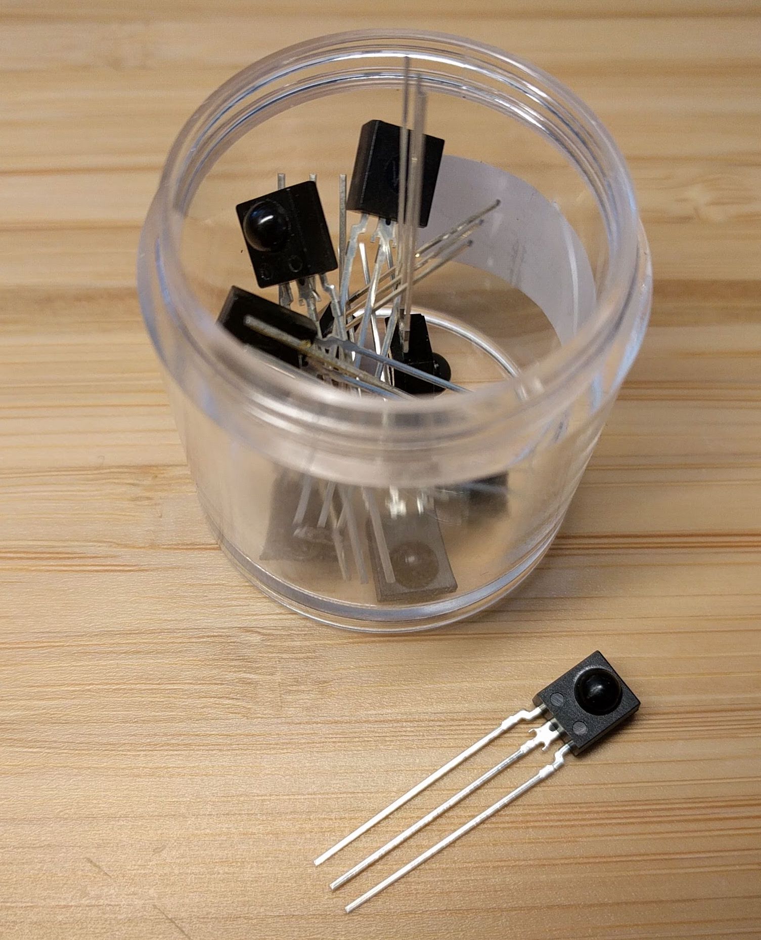
Your receiver looks more or less like this:</p>

<p><img src="/assets/20180722-ir-receiver-38khz.jpg" alt="20180722-ir-receiver-38khz.jpg" /></p>

<p>Pins are numbered from 1 to 3 starting from the left with the lens facing up. Connect pin 1 to <a href="https://pinout.xyz/">GPIO18 (pin 12) on the Raspberry Pi</a>, pin 2 to any GND/ground pin (6, 9, 14, 20, 25, 30, 34, 39 on the Raspberry Pi), and pin 3 to any 3.3V pin (1 or 17 on the Raspberry Pi).</p>

<h2 id="enable-the-gpio-ir-driver">Enable the gpio-ir driver</h2>

<p>Add the following to the end of your <code class="language-plaintext highlighter-rouge">/flash/config.txt</code> file:</p>

<div class="language-bash highlighter-rouge"><div class="highlight"><pre class="highlight"><code><span class="nv">dtoverlay</span><span class="o">=</span>gpio-ir
</code></pre></div></div>

<h2 id="assign-the-correct-keymap">Assign the correct keymap</h2>

<p>The linux kernel reads flashes from the IR remote and needs to translate them into events readable by Kodi.</p>

<p>Paste the following into the following file - <code class="language-plaintext highlighter-rouge">/storage/.config/rc_keymaps/a1156</code>:</p>

<div class="language-bash highlighter-rouge"><div class="highlight"><pre class="highlight"><code><span class="c"># table a1156, type: NEC</span>
0x87eeda0a KEY_UP
0x87eeda0c KEY_DOWN
0x87eeda05 KEY_ENTER
0x87eeda06 KEY_RIGHT
0x87eeda09 KEY_LEFT
0x87eeda03 KEY_ESC
</code></pre></div></div>

<p>Set up the keymap to be loaded as default by pasting the following into <code class="language-plaintext highlighter-rouge">/storage/.config/rc_maps.cfg</code>:</p>

<div class="language-bash highlighter-rouge"><div class="highlight"><pre class="highlight"><code><span class="k">*</span> <span class="k">*</span> a1156
</code></pre></div></div>

<h2 id="reboot-your-pi">Reboot your Pi</h2>

<p>Your kodi instance, once loaded should now respond to your Mac remote.</p>

<h3 id="troubleshooting-is-my-remote-sending-signals">Troubleshooting: Is my remote sending signals?</h3>

<p>Grab your smartphone and turn on your camera. Then point the camera at the IR LED in the remote and press a button. You should see flashes - if not,
your remote probably doesn’t work.</p>

<h3 id="troubleshooting-does-my-ir-receiver-work">Troubleshooting: Does my IR receiver work?</h3>

<p>Log into your Raspberry Pi and run <code class="language-plaintext highlighter-rouge">ir-ctl -r</code> and press some buttons on the remote. If you see a bunch of output like this, your remote is picked up by the IR receiver:</p>

<div class="language-bash highlighter-rouge"><div class="highlight"><pre class="highlight"><code>pulse 561
space 605
pulse 542
space 627
pulse 564
space 607
pulse 560
space 606
pulse 561
space 608
pulse 563
space 607
pulse 538
space 1756
pulse 569
space 601
pulse 562
</code></pre></div></div>]]></content><author><name>Jan Szumiec</name></author><summary type="html"><![CDATA[Got a remote like this one?]]></summary></entry><entry><title type="html">Increasing gRPC maximum message size (in Python)</title><link href="https://jasiek.me/2018/04/26/increasing-grpc-max-message-size" rel="alternate" type="text/html" title="Increasing gRPC maximum message size (in Python)" /><published>2018-04-26T00:00:00+02:00</published><updated>2018-04-26T00:00:00+02:00</updated><id>https://jasiek.me/2018/04/26/increasing-grpc-max-message-size</id><content type="html" xml:base="https://jasiek.me/2018/04/26/increasing-grpc-max-message-size"><![CDATA[<p>This is parked here for my future reference.</p>

<p>Problem statement: By default <a href="https://grpc.io">gRPC</a> will accept RPC message up to four megabytes in size. If you need to send anything bigger,
you will need to tweak some settings. There are two options which can be adjusted when creating a new server. This changes both the max incoming and outgoing
message size to 1 gigabyte:</p>

<div class="language-plaintext highlighter-rouge"><div class="highlight"><pre class="highlight"><code>gigabyte = 1024 ** 3

executor = futures.ThreadPoolExecutor()
server = grpc.server(executor, options=[
  ('grpc.max_send_message_length', gigabyte),
  ('grpc.max_receive_message_length', gigabyte)
])

</code></pre></div></div>]]></content><author><name>Jan Szumiec</name></author><summary type="html"><![CDATA[This is parked here for my future reference.]]></summary></entry><entry><title type="html">Creating footprints from actual parts in KiCad</title><link href="https://jasiek.me/2016/09/29/creating-footprints-from-actual-parts-in-kicad" rel="alternate" type="text/html" title="Creating footprints from actual parts in KiCad" /><published>2016-09-29T00:00:00+02:00</published><updated>2016-09-29T00:00:00+02:00</updated><id>https://jasiek.me/2016/09/29/creating-footprints-from-actual-parts-in-kicad</id><content type="html" xml:base="https://jasiek.me/2016/09/29/creating-footprints-from-actual-parts-in-kicad"><![CDATA[<p>Some time ago I sourced a number of very cheap SD card sockets from China for a hobby project I was working on.
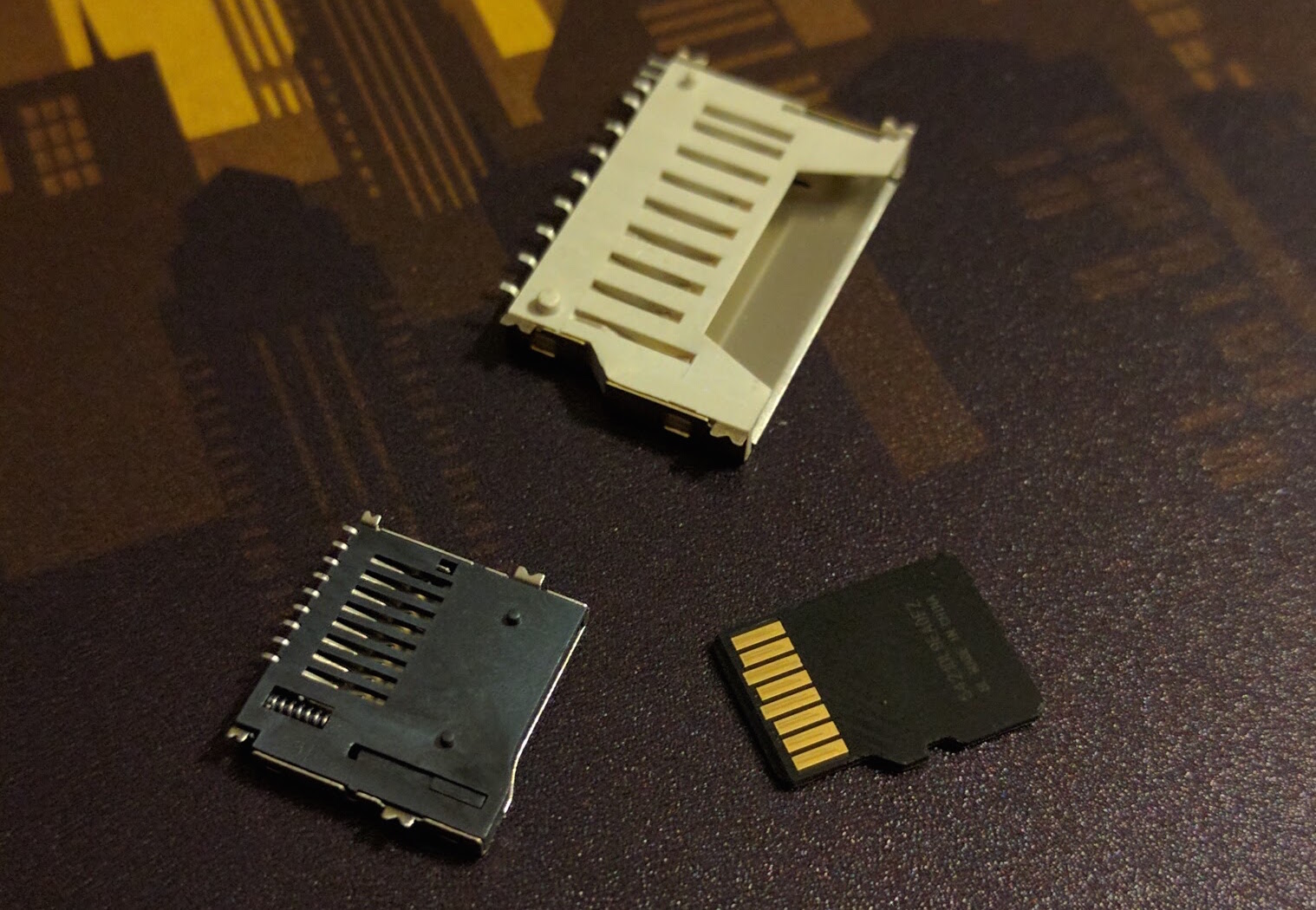
Sadly, when it came to PCB design, I couldn’t find the footprints for this particular socket anywhere - the part
being a proprietary invention of the factory rather than a cheap knockoff of a reputable brand like Amphenol
or Molex for which drawings are readily available off of snapeda.com.</p>

<p>Turns out, this is a problem with many, many parts - there are no CAD drawings to be found anywhere, and the
only way to really fit the part onto a board is to measure the part and draw everything yourself - a tedious
manual process, but with a few tools, any part can be precisely drawn and transferred onto the board.</p>

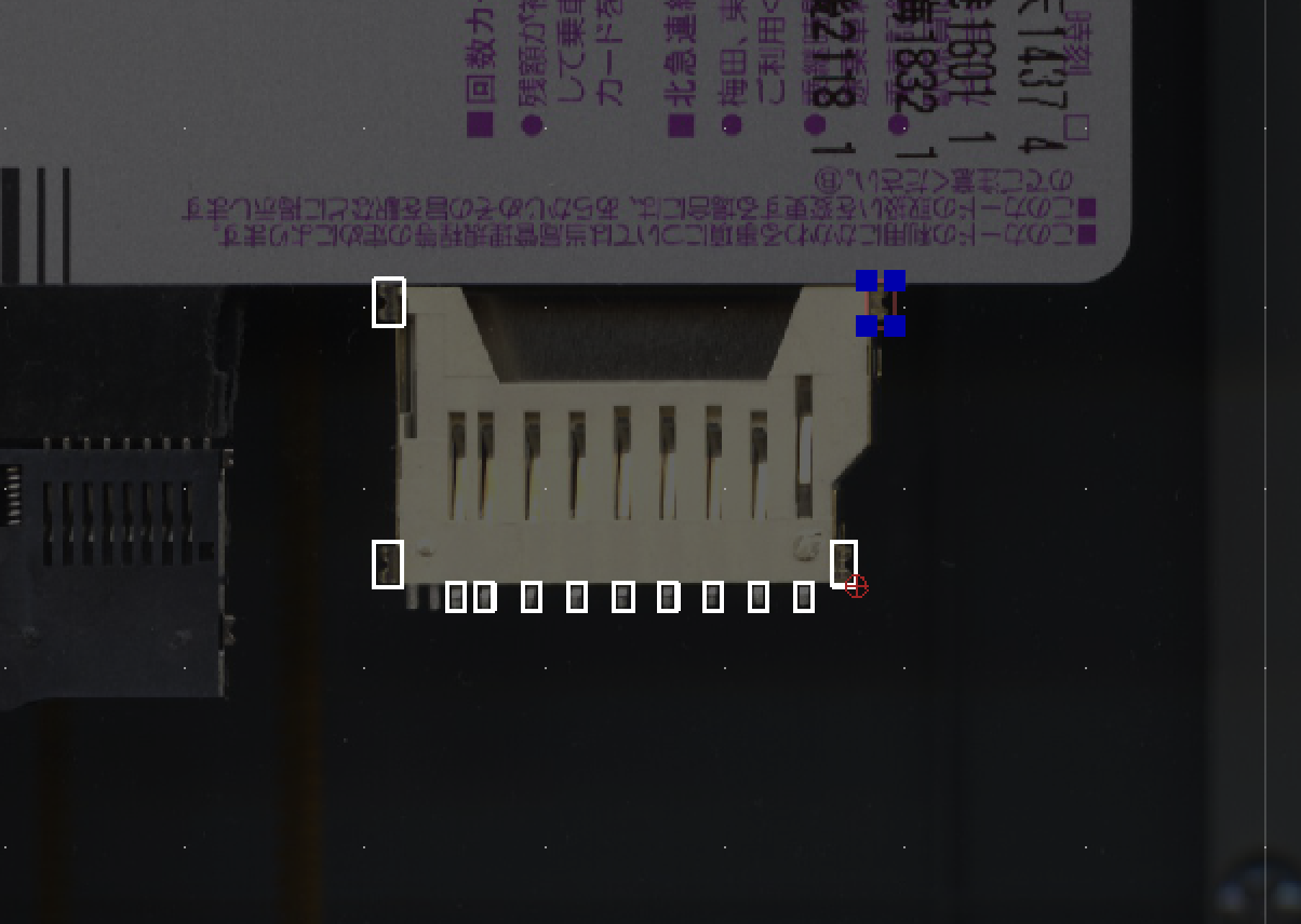
<p><img src="/assets/20160929-sd-card-slots.jpg" alt="20160929-sd-card-slots.jpg" /></p>

<h2 id="step-one---scan-the-part-using-a-flatbed-scanner">Step one - Scan the part using a flatbed scanner</h2>

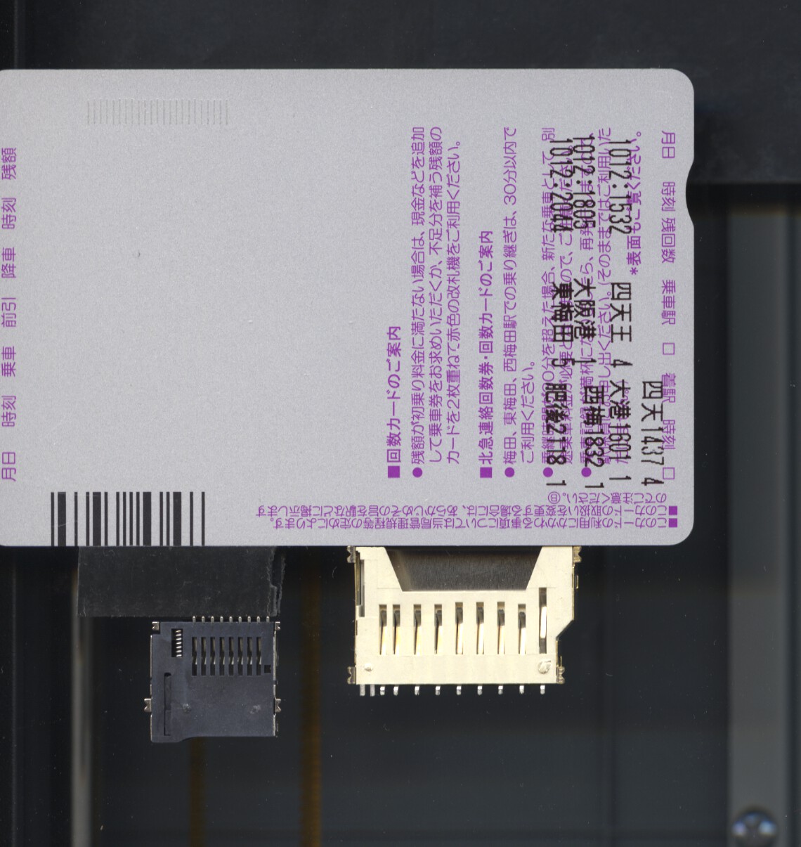
<p>In the absence of other tools, one can use any flatbed scanner to reproduce the measurements required to draw a
part. At 300dpi, a scan will yield a sufficient measurement on most, if not all parts. One key thing to remember
is to ensure that each part is aligned with the edge of the scanner - I’ve managed to accomplish this, using a
public transport card I’ve found in my drawer. Simply place the card (or any other rectangular item) next to the edge,
and make sure it touches it and is aligned with it, then - align your parts with the edges of the card.
The alternative is to use the edges of the scanner to align the parts, but I’ve found that to be unreliable.</p>

<p><img src="/assets/20160929-scan.jpg" alt="20160929-scan.jpg" /></p>

<h2 id="step-two---open-your-cad-package-and-import-the-bitmap">Step two - Open your CAD package and import the bitmap</h2>

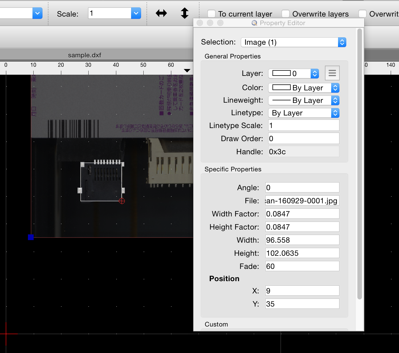
<p>Fire up your favorite CAD package (<a href="http://www.qcad.org">QCAD</a> is my choice), and import the bitmap. Ensure that it is scaled properly -
in my case (a 300 dpi) scan, the width/height factor turned out to be 0.0847 (300 dpi is 11.811 dots/mm,
and 1/11.811 = 0.08466683600033867).</p>

<p><img src="/assets/20160929-width-height-ratio.png" alt="20160929-width-height-ratio.png" /></p>

<h2 id="step-three---draw-your-part">Step three - draw your part</h2>

<p>Next, select the rectangle tool, and draw an outline over your first pad. There are a number of tools in QCAD
that make it easy to place copies of a pad equidistantly - use them, or place everything by hand.</p>

<p><img src="/assets/20160929-all-pads.png" alt="20160929-all-pads.png" /></p>

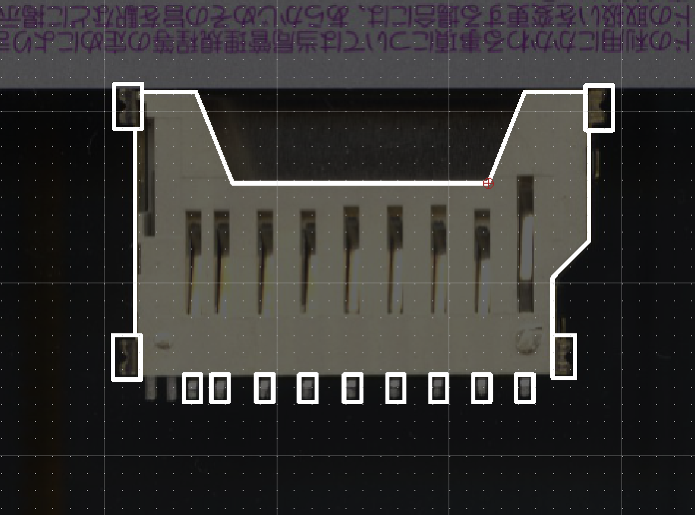
<p>Next, if you like, you can draw the outline of the part as well - this is useful for when you will want to transfer
it into KiCad’s footprint editor and place them on the silkscreen layer.</p>

<p><img src="/assets/20160929-outline.png" alt="20160929-outline.png" /></p>

<h2 id="step-four---export-as-dxf-and-import-into-kicad">Step four - export as DXF and import into KiCad</h2>

<p>Assuming you have saved your drawing as DXF, fire up KiCad, open the footprint editor, and select the library you
wish to place your future footprint in. Click on the “New footprint” icon, and select a name. Select File | Import DXF File,
select your file, and then select a layer you wish to import your drawing into - I’ve used ‘Dwgs.User’. The drawing
we import will be used to trace over, and will be removed later.</p>

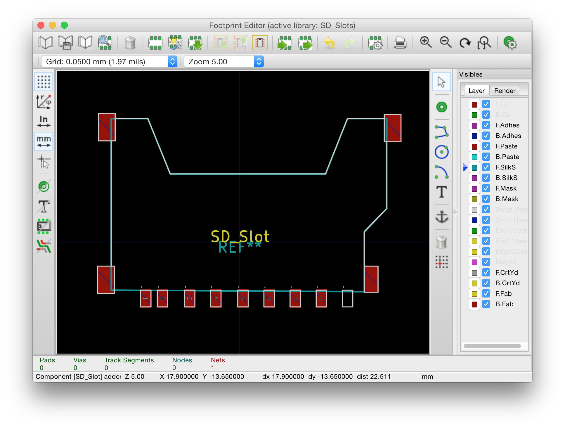
<p><img src="/assets/20160929-imported.png" alt="20160929-imported.png" /></p>

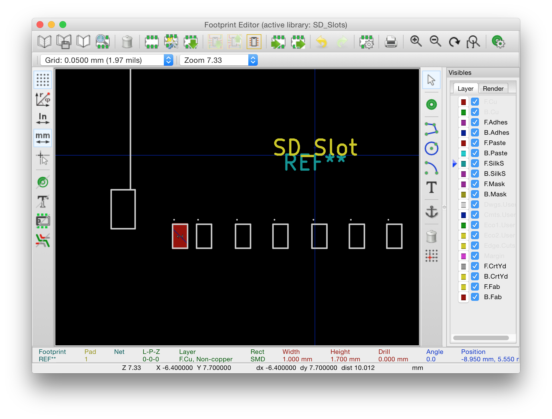
<h2 id="step-five---draw-your-pads-on-top-of-the-drawing-you-imported">Step five - draw your pads on top of the drawing you imported</h2>

<p>Select the pad placement tool, and place your first pad - click in the middle of a pad on the imported drawing and a
modal will pop up, prompting you to select the kind of pad, its name, dimensions, etc. In my case, I’ve selected a
rectangular SMD pad, entered the right dimensions through trial and error, and ended up with my first pad.</p>

<p><img src="/assets/20160929-pads.png" alt="20160929-pads.png" /></p>

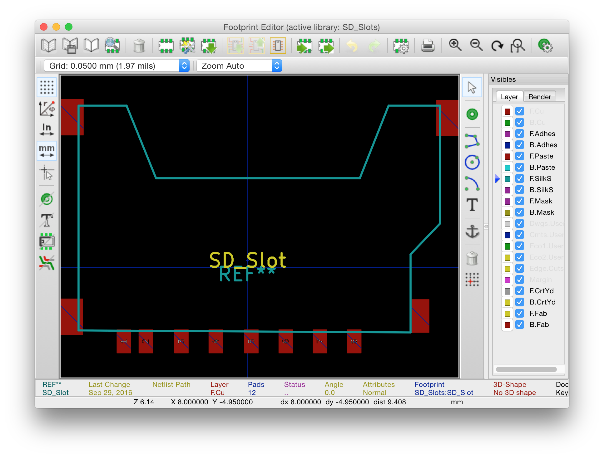
<p>When you’re finished drawing pads, you can proceed to the silkscreen layers to draw the outline of your part.</p>

<p><img src="/assets/20160929-silkscreen.png" alt="20160929-silkscreen.png" /></p>

<h2 id="step-six---remove-the-imported-drawing">Step six - remove the imported drawing</h2>

<p>Since we no longer need it for anything - you can remove the drawing you imported from QCAD. There’s no good way to
remove all line segments using the footprint editor, other than manually removing them by hand. Fortunately, kicad_mod
files are just what appears to be LISP code - meaning you can simply remove all lines with ‘Dwgs.User’ in them.
Edit them out and save the file - you’ll need to restart KiCad for these changes to be refreshed within the footprint
editor.</p>

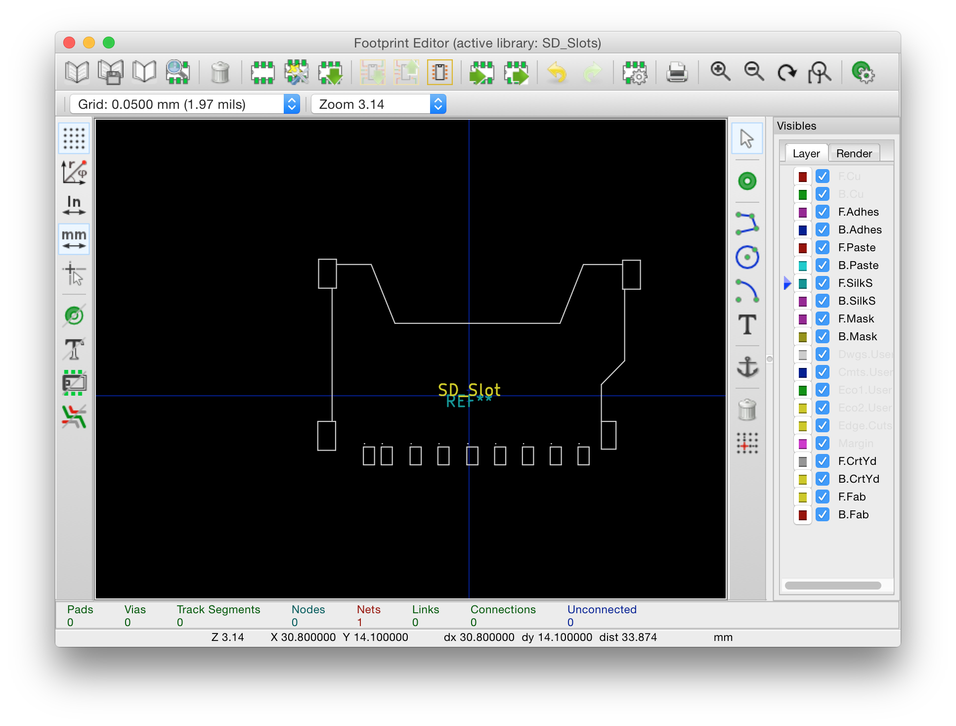
<h2 id="step-seven---youre-done">Step seven - you’re done</h2>

<p><img src="/assets/20160929-done.png" alt="20160929-done.png" /></p>

<p>Assuming you have arrived here - your part is ready to be associated with components and placed on the PCB. This process
took me approximately 15 minutes from start to finish, including scanning.</p>]]></content><author><name>Jan Szumiec</name></author><summary type="html"><![CDATA[When you can't get ahold of KiCad footprints for certain parts, use a scanner to drawn your own]]></summary></entry><entry><title type="html">Running a WeMOS/NodeMCU off a 18650 battery</title><link href="https://jasiek.me/2016/04/24/running-wemos-nodemcu-off-a-18650-battery" rel="alternate" type="text/html" title="Running a WeMOS/NodeMCU off a 18650 battery" /><published>2016-04-24T00:00:00+02:00</published><updated>2016-04-24T00:00:00+02:00</updated><id>https://jasiek.me/2016/04/24/running-wemos-nodemcu-off-a-18650-battery</id><content type="html" xml:base="https://jasiek.me/2016/04/24/running-wemos-nodemcu-off-a-18650-battery"><![CDATA[<p>I’ve been working on adding random sensors of all kinds around my house to gather data and plot nice graphs.
Given how cheap NodeMCU clones have gotten, I’ve decided to get ten and play with them - a month later I received
“WeMos LoLin” boards, which are essentially a clone of a clone of a NodeMCU v3 board. They’re great - just plug
in via USB and get to work!</p>

<p>Prior to ordering these, I’ve put together really simple temperature sensors using bare ESP12F modules - combined
with a MCP1700 voltage regulator, I could hook them up to a 18650 Lithium Ion battery and leave them running for
around a month (using deep sleep, naturally).</p>

<h3 id="wemos-cant-be-operated-from-a-18650-out-of-the-box">WeMos can’t be operated from a 18650 out of the box</h3>

<p>I was disappointed to discover that my WeMos module wouldn’t work when plugged in directly to a battery - upon
further investigation, I’ve discovered that the regulator used on the board was <a href="http://www.advanced-monolithic.com/pdf/ds1117.pdf">AMS1117-3.3</a></p>
<ul>
  <li>which has a dropout voltage of 1V. This meant that a fully charged 18650 would only work for a few minutes at most.</li>
</ul>

<p>The solution was to replace the regulator on the board with a low-dropout regulator - the <a href="http://ww1.microchip.com/downloads/en/DeviceDoc/20001826C.pdf">MCP1700</a>.
This required 5 minutes of soldering. It’s a shame I couldn’t find another regulator in a SOT-223 package whose
pinout would be the same as the AMS1117 - so had bend the pins a bit to make everything fall into place.</p>

<p><img src="/assets/20160424-wemos.jpg" alt="20160424-wemos.jpg" /></p>

<h3 id="enabling-deep-sleep-on-the-wemos">Enabling deep sleep on the WeMos</h3>

<p>Out of the box, if you put the module to deep sleep, it will just stay there doing nothing forever. What
you need to do is to wire the D0 pin (GPIO16/WAKE) to the RST pin.</p>

<h3 id="the-new-wemos-d1-is-much-better">The new WeMos D1 is much better</h3>

<p>The <a href="http://www.wemos.cc/Products/d1_mini.html">WeMos D1 mini</a> uses a regulator with a dropout voltage of
just 250mV (the <a href="http://www.richtek.com/Products/Linear%20Regulator/Single%20Output%20Linear%20Regulator/RT9013">RT9013</a>,
so you can wire it directly with a battery, and everything will work nicely out of the box.</p>]]></content><author><name>Jan Szumiec</name></author><summary type="html"><![CDATA[How to modify an off-the-shelf, cheap chinese board to run off a lithium battery for days]]></summary></entry><entry><title type="html">Decoupling capacitors for the win!</title><link href="https://jasiek.me/2016/02/27/decoupling-capacitors-for-the-win" rel="alternate" type="text/html" title="Decoupling capacitors for the win!" /><published>2016-02-27T00:00:00+01:00</published><updated>2016-02-27T00:00:00+01:00</updated><id>https://jasiek.me/2016/02/27/decoupling-capacitors-for-the-win</id><content type="html" xml:base="https://jasiek.me/2016/02/27/decoupling-capacitors-for-the-win"><![CDATA[<p>While working on a VGA adapter for a Z80-based computer I’m building, I started out by assembling a very simple circuit
for generating VGA signal based on the <a href="https://en.wikipedia.org/wiki/Parallax_Propeller">Parallax Propeller</a>. I’ve put
it together and loaded one of the sample programs for displaying text. It didn’t work, and I couldn’t figure out why.
At first, I tried running the test program in different resolutions - that worked - but the screen was wobbly.</p>

<p><img src="/assets/20160227-wobbliness.jpg" alt="20160227-wobbliness.jpg" /></p>

<p>That led me to think that there was a problem with timings. I looked at my oscilloscope, but the timings for VSYNC
and HSYNC were okay. One thing I noticed however, was that there was a lot ripple on the PSU:</p>

<p><img src="/assets/20160227-ripple1.png" alt="20160227-ripple1.png" /></p>

<p>I’ve then added one 100nF ceramic capacitor where the PSU meets the board, and got this:</p>

<p><img src="/assets/20160227-ripple2.png" alt="20160227-ripple2.png" /></p>

<p>Better, but I wonder what would happen if I added another cap of the same size to where the Propeller meets the PCB. I’ve
added that, and got this:</p>

<p><img src="/assets/20160227-ripple3.png" alt="20160227-ripple3.png" /></p>

<p>Looks <em>much</em> better, doesn’t it? I loaded up the original test program, running 800x600 at 75Hz and got a nearly perfect image.</p>

<iframe width="560" height="315" src="https://www.youtube.com/embed/ILlRLrflUOY" frameborder="0" allowfullscreen=""></iframe>]]></content><author><name>Jan Szumiec</name></author><summary type="html"><![CDATA[How I fixed my work-in-progress VGA adapter using two 100nF caps]]></summary></entry><entry><title type="html">Drilling PCBs using the Shapeoko</title><link href="https://jasiek.me/2016/02/20/drilling-pcbs-using-the-shapeoko" rel="alternate" type="text/html" title="Drilling PCBs using the Shapeoko" /><published>2016-02-20T00:00:00+01:00</published><updated>2016-02-20T00:00:00+01:00</updated><id>https://jasiek.me/2016/02/20/drilling-pcbs-using-the-shapeoko</id><content type="html" xml:base="https://jasiek.me/2016/02/20/drilling-pcbs-using-the-shapeoko"><![CDATA[<p>My <a href="https://london.hackspace.org.uk">local hackspace</a> has a <a href="http://www.shapeoko.com/wiki/index.php/ShapeOko_2">Shapeoko 2</a> CNC mill, which I started to use
recently to make PCBs. There are two ways in which the Shapeoko can help: it can either mill out the tracks, or drill the holes for THT components.
In this writeup I’ll concentrate on the latter, as I still use a regular UV exposure based process for drawing tracks.</p>

<p>I’m assuming you’ve created a PCB project with some kind of EDA software - my favorite is <a href="http://kicad-pcb.org/">KiCad</a>, and that’s what I’ll base this tutorial
on. I’ll take it you’ve already laid out your components and tracks using pcbnew and you’re ready to export you design. Before we export it, let’s make a few
small adjustments that will make our work with other complementary packages (<a href="http://flatcam.org/">FlatCAM</a>, <a href="https://github.com/vlachoudis/bCNC">bCNC</a>) easier.</p>

<h3 id="prep-your-design-within-kicad">Prep your design within KiCad</h3>

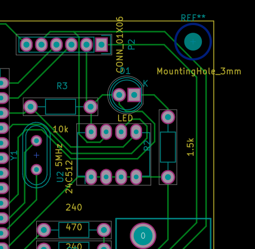
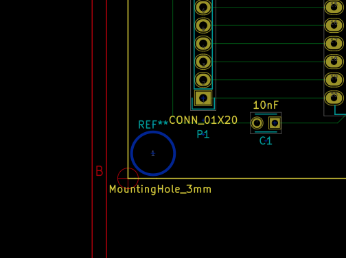
<p>First - make sure you’ve added mounting holes to your design. Now, I do realize that many boards are just quick projects where you don’t really care about having
those, as you’ll glue it to whatever using a glue stick or some epoxy - but trust me - this will save you a headache and possibly a lot of PCB laminate later on.
The reason for this is that once you generate a <a href="https://en.wikipedia.org/wiki/G-code">G-code</a> representation of the holes to be drilled, you’ll be able to easily
identify the boundaries of the board
and you’ll be able to easily tell beyond which area no holes will be drilled so you can reuse whatever PCB off-cuts you have left from other projects, and you’ll
be able to figure out where to place any mounting brackets you’ll use to keep the board in place. You don’t need to worry too much about the diameter - I usually
select 3mm which in my process results in 1mm “placeholder” holes being drilled, which I then use as a guide to drill the final 3mm hole using a manual pillar drill.</p>

<p><img src="/assets/20160220-mounting-hole.png" alt="20160220-mounting-hole.png" /></p>

<p>Secondly - place the origin in one of the corners of the board - it makes later positioning easier. Which corner you want to place it in depends on how your board
will be mounted to the CNC working area - if you install a bracket on the right side of the board, you probably want to set the origin to a corner on the left, and
vice versa.</p>

<p><img src="/assets/20160220-origin.png" alt="20160220-origin.png" /></p>

<h3 id="export-your-design-from-kicad">Export your design from KiCad</h3>

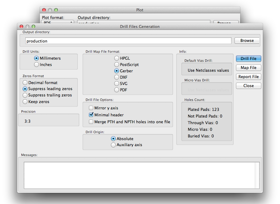
<p>Once you’ve done that, you’re ready to export your design as a <a href="https://en.wikipedia.org/wiki/Gerber_format">Gerber file</a> for drilling. The file contains tool
definitions (what size drill to use to drill each hole) and for each tool, a list of hole coordinates to be drilled. This would all be enough, but to actually
make a hole in the board we need to add another dimension - depth.</p>

<p><img src="/assets/20160220-plot-drill.png" alt="20160220-plot-drill.png" /></p>

<h3 id="import-into-flatcam">Import into FlatCAM</h3>

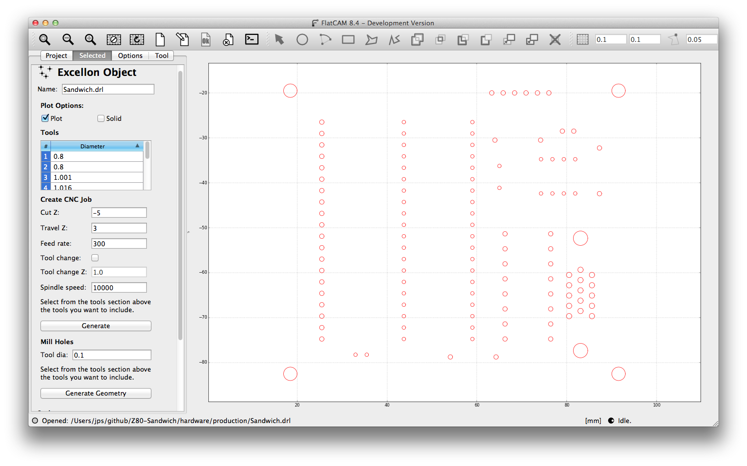
<p>FlatCAM is a tool specifically designed for preparing PCB milling jobs on CNC machinery. In this writeup, we’ll focus on a very small subset of its functionality.
First, open the file you generated using KiCad, by selecting <em>File | Open Excellon…</em>. Within the project pane, you’ll see your imported file. Select it by double-clicking.
Your design will appear on the right.</p>

<p><img src="/assets/20160220-excellon.png" alt="20160220-excellon.png" /></p>

<p>You <em>may</em> want to adjust the location of the design in respect to coordinates, by using the offset input field if you run into problems positioning your
design within bCNC. The options selected in the view below correspond to drilling holes 5mm into the board, and retracting 3mm above the surface of the board when
moving the drill from hole to hole. I’ve set the spindle speed to 10000 rpm, but it seems that our Shapeoko maxes out at ca 3000. Once done, click on ‘Generate’.
You should end up with a <code class="language-plaintext highlighter-rouge">drl_cnc</code> file which is your drilling project. If you can’t see that in the Project pane, you’ve done something wrong and need to try again.</p>

<h3 id="generate-g-code-from-flatcam">Generate G-code from FlatCAM</h3>

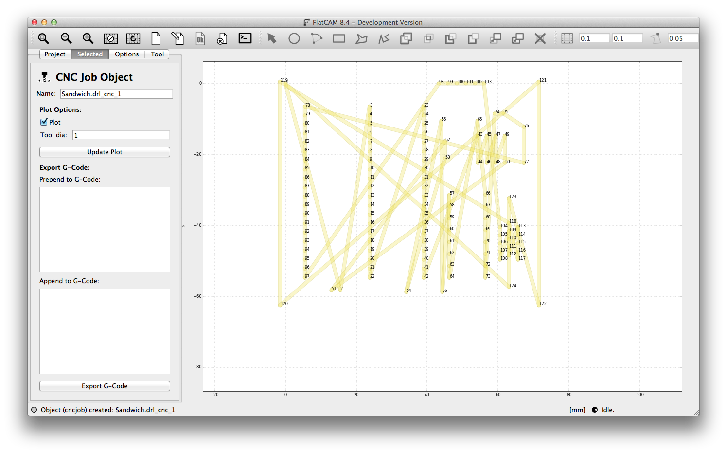
<p>Click on the generated <code class="language-plaintext highlighter-rouge">drl_cnc</code> file and set the tool diameter to 1mm - this is probably not absolutely necessary. Then, click on <code class="language-plaintext highlighter-rouge">Export G-Code</code>, and select
the location where you want to save your file.</p>

<p><img src="/assets/20160220-cnc-job.png" alt="20160220-cnc-job.png" /></p>

<h3 id="import-your-g-code-into-bcnc">Import your G-code into bCNC</h3>

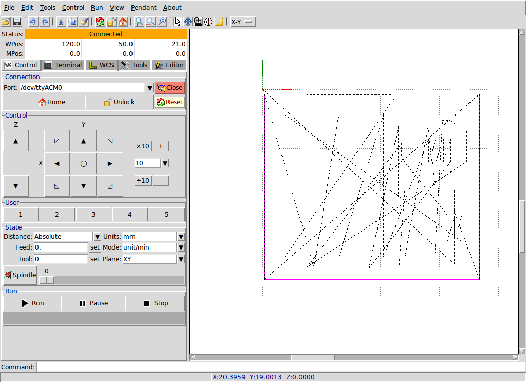
<p>Fire up bCNC and open the file you generated. You should see your design in form of a mesh of dashed lines. You can explore different views by selecting a view profile
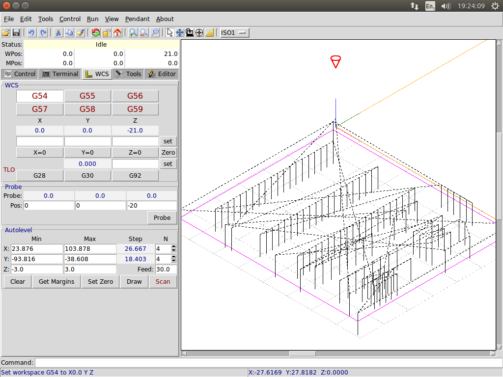
from a drop-down menu next to zoom buttons above the graph. Have a look at ISO1 - you should be able to see where the holes are going to be and where the software
<em>thinks</em> where the machine head is. This is absolutely crucial - whenever you power on the machine, the head may have been moved manually, and you must tell bCNC
where, in relation to your PCB the head is. If you fail to do that the following may happen: you’ll break the drill bit, destroy the board, start a fire, or destroy
the machine an injure yourself. Pay attention and avoid a freak accident.</p>

<p><img src="/assets/20160220-bcnc1.png" alt="20160220-bcnc1.png" /></p>

<p>First, retract the drill by pressing Z arrow up. Once the drill is in the air, position and lock down your PCB to the sacrificial layer (usually a piece of wood).
Then, lower the drill to about 5mm above the surface of the PCB. If you haven’t touched the X &amp; Y arrows yet the drill should be in its starting position, as indicated
by a small cone on the ISO1 view. Here’s the tricky bit: we will be zero-ing each axis, so what you need to do, is to position the drill above the actual starting
position on the PCB. In my case, it’ll be the top left corner of the board.</p>

<p><img src="/assets/20160220-bcnc2.png" alt="20160220-bcnc2.png" /></p>

<p>Once you’re happy with the X &amp; Y position of the drill, you can zero it using the <code class="language-plaintext highlighter-rouge">X=0</code> and <code class="language-plaintext highlighter-rouge">Y=0</code> buttons. The cone, or circle indicating the position of the drill
should now move back to the top-left location where it was initially. The only thing left to do now, is to set the position of the Z-axis. There are two ways of doing
this. You can either gradually lower the drill using Z arrows to where the drill touches the board (with this comes risk of breaking the drill bit, so be careful),
or alternatively, you can loosen the drill bit, let it fall to the surface of the PCB and tighten it. Once you’re happy with the vertical position of the drill bit,
you can zero the position of the Z axis, by clicking on the <code class="language-plaintext highlighter-rouge">Z=0</code> button.</p>

<h3 id="drill">Drill</h3>

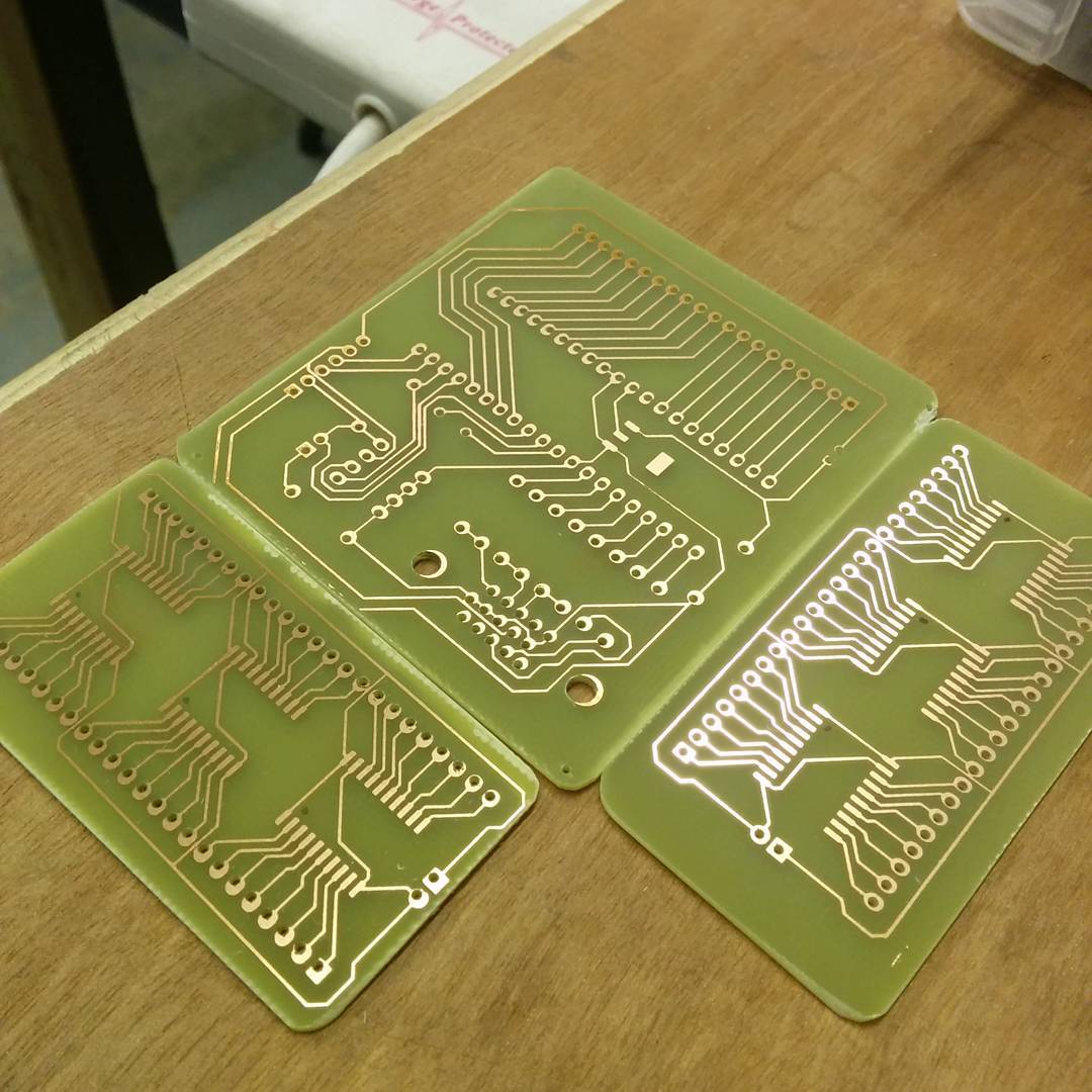
<p>Press the play button to commence your drilling. Depending on the size of the board, number of holes, and feed rate, it will take different amounts of time. In my case,
I’ve managed to drill 120 holes on a 8 by 8 cm board in about eight minutes.</p>

<p><img src="/assets/20160220-final.jpg" alt="20160220-final.jpg" /></p>]]></content><author><name>Jan Szumiec</name></author><summary type="html"><![CDATA[Quick and dirty introduction to drilling holes using a Shapeoko 2 CNC mill using FlatCAM and bCNC]]></summary></entry></feed>