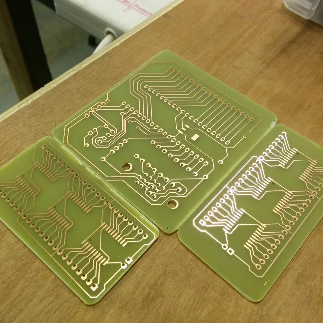
My local hackspace has a Shapeoko 2 CNC mill, which I started to use recently to make PCBs. There are two ways in which the Shapeoko can help: it can either mill out the tracks, or drill the holes for THT components. In this writeup I’ll concentrate on the latter, as I still use a regular UV exposure based process for drawing tracks.
I’m assuming you’ve created a PCB project with some kind of EDA software - my favorite is KiCad, and that’s what I’ll base this tutorial on. I’ll take it you’ve already laid out your components and tracks using pcbnew and you’re ready to export you design. Before we export it, let’s make a few small adjustments that will make our work with other complementary packages (FlatCAM, bCNC) easier.
Prep your design within KiCad
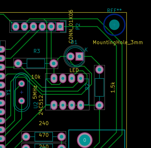
First - make sure you’ve added mounting holes to your design. Now, I do realize that many boards are just quick projects where you don’t really care about having those, as you’ll glue it to whatever using a glue stick or some epoxy - but trust me - this will save you a headache and possibly a lot of PCB laminate later on. The reason for this is that once you generate a G-code representation of the holes to be drilled, you’ll be able to easily identify the boundaries of the board and you’ll be able to easily tell beyond which area no holes will be drilled so you can reuse whatever PCB off-cuts you have left from other projects, and you’ll be able to figure out where to place any mounting brackets you’ll use to keep the board in place. You don’t need to worry too much about the diameter - I usually select 3mm which in my process results in 1mm “placeholder” holes being drilled, which I then use as a guide to drill the final 3mm hole using a manual pillar drill.
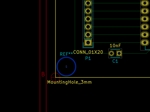
Secondly - place the origin in one of the corners of the board - it makes later positioning easier. Which corner you want to place it in depends on how your board will be mounted to the CNC working area - if you install a bracket on the right side of the board, you probably want to set the origin to a corner on the left, and vice versa.
Export your design from KiCad
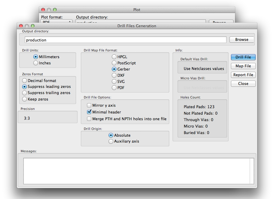
Once you’ve done that, you’re ready to export your design as a Gerber file for drilling. The file contains tool definitions (what size drill to use to drill each hole) and for each tool, a list of hole coordinates to be drilled. This would all be enough, but to actually make a hole in the board we need to add another dimension - depth.
Import into FlatCAM
FlatCAM is a tool specifically designed for preparing PCB milling jobs on CNC machinery. In this writeup, we’ll focus on a very small subset of its functionality. First, open the file you generated using KiCad, by selecting File | Open Excellon…. Within the project pane, you’ll see your imported file. Select it by double-clicking. Your design will appear on the right.
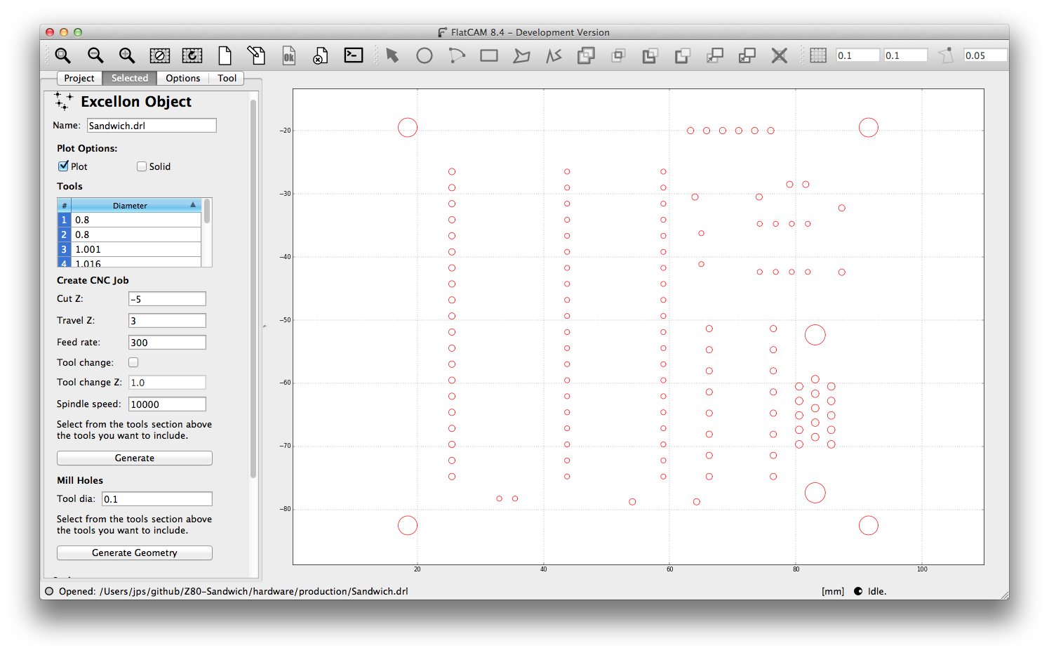
You may want to adjust the location of the design in respect to coordinates, by using the offset input field if you run into problems positioning your
design within bCNC. The options selected in the view below correspond to drilling holes 5mm into the board, and retracting 3mm above the surface of the board when
moving the drill from hole to hole. I’ve set the spindle speed to 10000 rpm, but it seems that our Shapeoko maxes out at ca 3000. Once done, click on ‘Generate’.
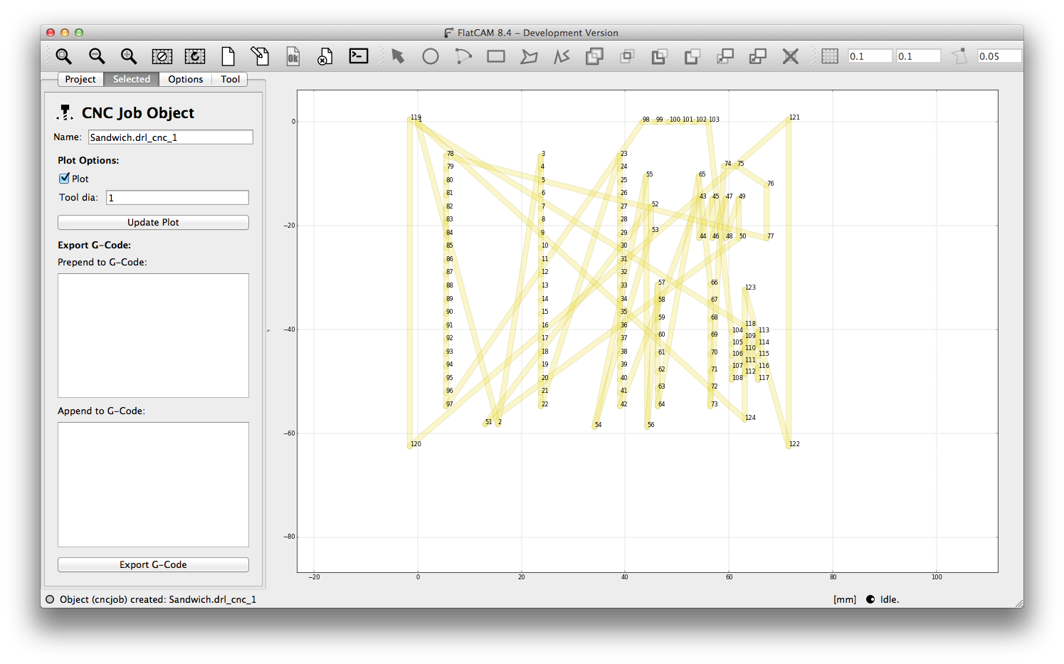
You should end up with a drl_cnc file which is your drilling project. If you can’t see that in the Project pane, you’ve done something wrong and need to try again.
Generate G-code from FlatCAM
Click on the generated drl_cnc file and set the tool diameter to 1mm - this is probably not absolutely necessary. Then, click on Export G-Code, and select
the location where you want to save your file.
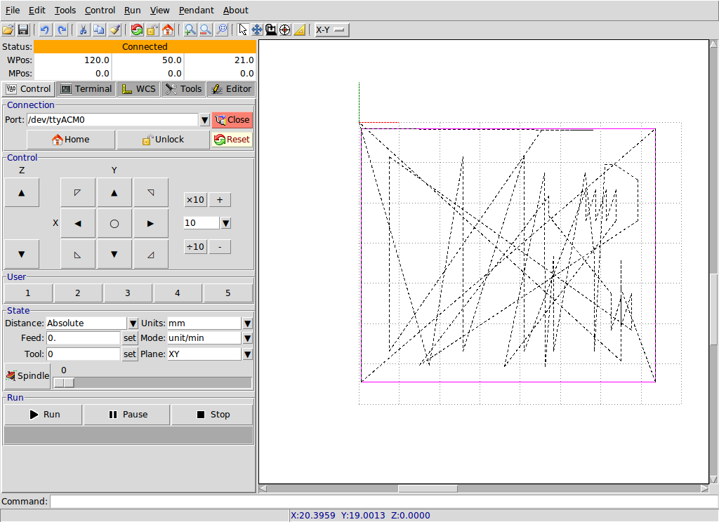
Import your G-code into bCNC
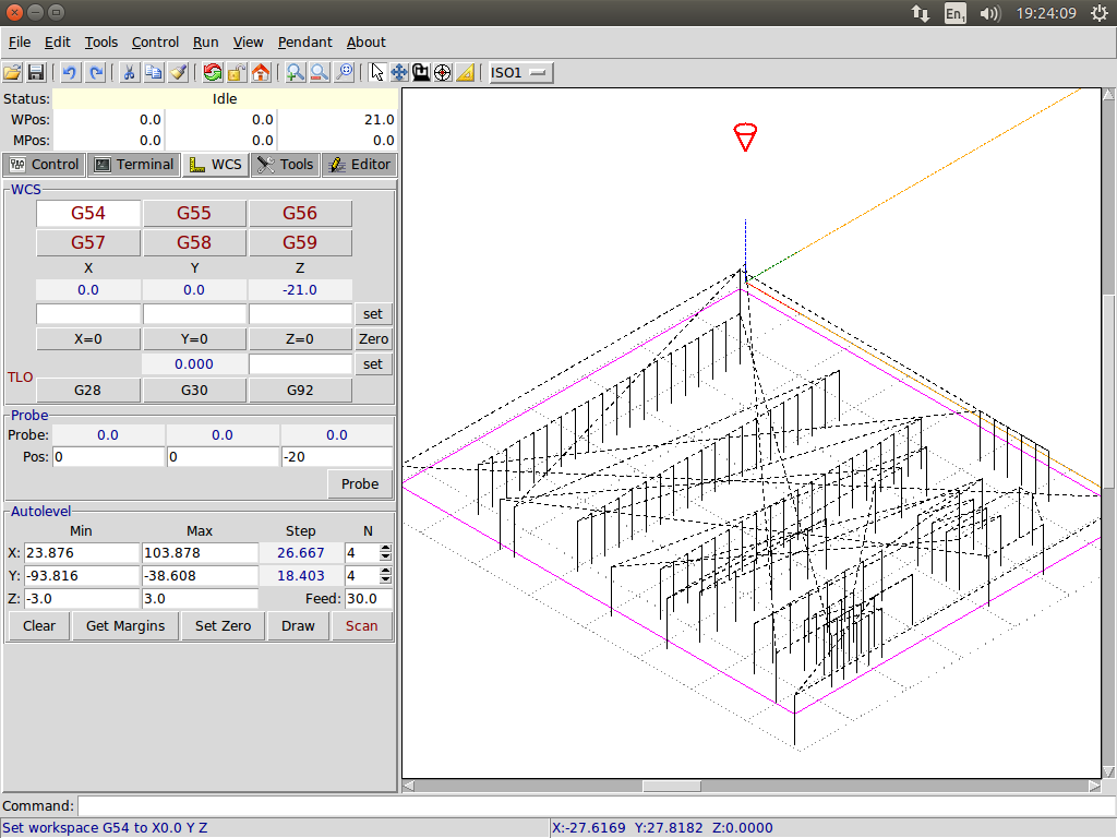
Fire up bCNC and open the file you generated. You should see your design in form of a mesh of dashed lines. You can explore different views by selecting a view profile from a drop-down menu next to zoom buttons above the graph. Have a look at ISO1 - you should be able to see where the holes are going to be and where the software thinks where the machine head is. This is absolutely crucial - whenever you power on the machine, the head may have been moved manually, and you must tell bCNC where, in relation to your PCB the head is. If you fail to do that the following may happen: you’ll break the drill bit, destroy the board, start a fire, or destroy the machine an injure yourself. Pay attention and avoid a freak accident.
First, retract the drill by pressing Z arrow up. Once the drill is in the air, position and lock down your PCB to the sacrificial layer (usually a piece of wood). Then, lower the drill to about 5mm above the surface of the PCB. If you haven’t touched the X & Y arrows yet the drill should be in its starting position, as indicated by a small cone on the ISO1 view. Here’s the tricky bit: we will be zero-ing each axis, so what you need to do, is to position the drill above the actual starting position on the PCB. In my case, it’ll be the top left corner of the board.
Once you’re happy with the X & Y position of the drill, you can zero it using the X=0 and Y=0 buttons. The cone, or circle indicating the position of the drill
should now move back to the top-left location where it was initially. The only thing left to do now, is to set the position of the Z-axis. There are two ways of doing
this. You can either gradually lower the drill using Z arrows to where the drill touches the board (with this comes risk of breaking the drill bit, so be careful),
or alternatively, you can loosen the drill bit, let it fall to the surface of the PCB and tighten it. Once you’re happy with the vertical position of the drill bit,
you can zero the position of the Z axis, by clicking on the Z=0 button.
Drill
Press the play button to commence your drilling. Depending on the size of the board, number of holes, and feed rate, it will take different amounts of time. In my case, I’ve managed to drill 120 holes on a 8 by 8 cm board in about eight minutes.